
This mobile phone detector can sense the presence of an activated mobile phone from a distance of four to five metres. So it can come handy in an examination hall or meetings where mobile phones are not permitted.
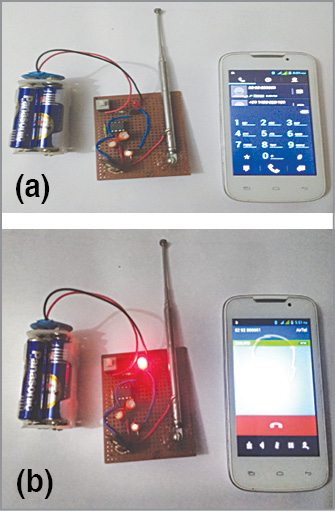
The circuit can detect incoming and outgoing calls, SMSes, Internet and video transmissions even if a mobile phone is kept in silent mode. When it detects an RF signal from an activated mobile phone, its LED starts blinking and continues to blink until the signal stops. The author’s prototype is shown in Fig. 1.
Circuit diagram of the mobile phone detector using LM358 is shown in Fig. 2. It is built around LM358 (IC1) and npn transistor BC548 (T1).
- Advertisement -
When a mobile phone is active, it radiates RF signal that passes through nearby space. The signal contains electromagnetic RF radiation from the phone.
Capacitor C1 is used in the circuit to detect the RF signal from the mobile phone. When the mobile phone radiates energy in the form of RF signal, C1 absorbs it and passes on to the inputs of IC1. This is indicated by the flashing of LED1. Preset VR1 (2.2M) is used to vary the range of the circuit. Transistor T1 is used to amplify the signal obtained at pin 1 of IC1.
The circuit is applicable for 2G networks, GPRS and network search (manual/automatic). It does not detect 3G, WCDMA and HSDPA network signals so well.
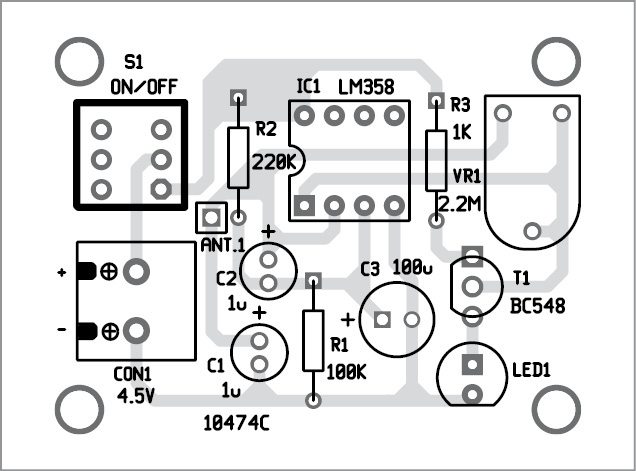
A single-side PCB layout for the mobile phone detector circuit is shown in Fig. 3 and its component layout in Fig. 4. After assembling the circuit on the PCB, enclose it in a suitable plastic box.

The circuit works off a 4.5V DC power supply.
Kumar Abhisekh is an electronics hobbyist
WANTS TO MARKETING OF YOUR PRODUCTS, i.e. GENERATION OF NEW BUYER’S, SO OUR SELL WILL INCREASE. EXPERINECE OF 20 YEARS IN FIELD MARKETING.
Dear Pramit, please wait for 2-3 business days as I have forwarded your question to the concerned person.
Sir, plss tell me what if in case the mobile phone is neither receiving message or calls nor the data is turned on..In this scenario the person is using the phone but it won’t be detected by our detector..Is there any other circuit which will sense the mobile network..Nd also something which will sense the presence of a mobile phone which is on flight mode?
The circuit will not detect your mobile phone if it is not activated in normal mode or working mode. It will not detect in flight mode because this circuit can detect mobile phone only through its incoming and outgoing signals.
sir there is any circuit that receive audio that we are talking buy call Sir there is any circuit that receive audio what we are talking in by callWhy it does not work well for 3G whereas 3G is also an RF signal like 2G ? And modifications in it can make it work for 3G also…?
how much range for this circuit that it will detect an mobile phone….This mobile phone detector can sense the presence of an activated mobile phone from a distance of four to five metres.
Can 1 mOhm Potentiometr to be used? Can this circuit be done on a simple breadboard? What’s the replacement for 4.5 volt battery?4.5V power supply is required in the circuit, it can be AC/DC adaptor having 4.5V output, it can be three 1.5V battery cell or it can be a single 4.5V lead acid battery. You can also try with 9V battery, it will work but in that case a slight changes may be required in the circuit.
Sir,My own circuit from your made have turn on with just plug in the battery (9v).On my home have WiFi connection.So what’s wrong with my own??
very nice project, can i detect any mobile without in calling . What is the maximum range of this circuit
Hello Sir ,
I appreciate for you nice concept and I would like to know whether I can use a strip antenna while designing a PCB
Good afternoon, i noticed the parts list calls for (2) 1uF electrolytic capacitors can i use 1 uF ceramic capacitors instead?
Hlo sir.Hello sir. While im attempting this project, Once the LED gets ON it never gets OFF i think it is due to charging of parallel capacitor and it not detect the incoming signal from mobile
What are the uses of other capacitors?C2 and C3 LM358 pin daigram please photo sendhello sir..i appreciated your project and pcb..
sir i want to work with u..now i m pursiung b.tech 4th yr.
and i interested in this field…so thats why this region i chooses ec branch..and i have knowledge electronics component and already i took training with PCB design and EMBEDDED system.
Do you mind explaining the rest of the circuit. Only C1 and T1 are explained. Does the amplifier convert current to voltage ?
The antenna goes direct into a grounding capacitor then into a chip with a 1 MHz rating.
Can somebody explain this ?
What does ic LM358 work as in this project. I mean does it work as comparator, amplifier or something else
LM358 is used as an operational amplifier in this project.does the operational amplifier work as a comparator or current to voltage converter or something else. also can you give the design equations with which you have selected the values for the resistors and capacitors.
Hey.
I implemented the circuit and it worked but after few minutes the Led remain constantly ON.. Like one of the capacitor is charged already.. How can I make it discharge so to maintain proper work
Vary the wiper of VR1 preset left and then right. If LED still continuous to glow, first check proper connection of VR1 or replace VR1 with fresh one. If problem persists, you can check transistor T1 or replace it. No need to manually discharge capacitors.
In fact, T1 is acting as a switch. It is the LM358 which amplifies the AC signal from the antenna, not the BJT. When the output of the LM is high enough ( from the datasheet, 3.3 volt if the battery is 5 Volt, which is close to the 4.5 V used here) the BJT let pass the current and the LED turns on. When its output is low (as high as 20mV, from the datasheet), that is not enough, so the BJT turns off, and so the LED. Note: you should place the LED on the collector side, not on the emitter side. As it is, the output of the LM of 3.3 Volt has to be bigger than Vbe_on of the BJT (say 0.6 V ) plus the tension drop at the LED. So your LED won’t turn on, as it is, if its voltage drop is larger than 3.3 – 0.6, or 2.7 Volt. About the left part of the circuit. Make a DC analysis, that is, remove the AC source (the antenna), and the capacitors and the then dangling wires, and you should see a standard OpAmp circuit. R2 and R1 makes a voltage divider (for the AC signal that will be added to the DC constant state), with IN1+ connected at the “middle” point, the point between R2 and R1. IN1- is connected to the negative feedback controlled by VR1. You will adjust VR1 to “just” light on the LED. For the AC analysis, remove the DC source and replace it with a ground. Replace the capacitors with a plain wire, for the first glance. That is legitimated by the fact that at high frequency, the capacitors let the voltage pass through with much … “resistance” (reactance). If you do that, you will see that IN1+ and IN1- are now connected by a wire. So, at the same voltage. What is the output of an OpAmp in this case? It produces a 0 volt output (well, can be up to 20 mV for this LM in this configuration), but in any case, then, this is not enough to turn on the BJT. The BJT performs like a switch, and no more current flow through the LED. Now, the capacitors are not really plain wires. C2 and C3 won’t charge up at the same speed and will also create a voltage offset (phase) so that at any moment, the AC component (superposed to the DC constant state) voltage at IN1- will be lightly off with the one at IN1+. Sometimes that will be just enough to generate an output from the OpAmp to switch on the BJT, sometimes the difference won’t be enough and the OpAmp will output not enough voltage to switch on the BJT. What are the design considerations: R1 cannot be 0, the IN1+ voltage could drop below 0 volt, under AC, and destroy the OpAmp. Generally, we try R1 = R2, more or less, in order to cover the AC voltage swing on both sides of the middle of the DC supplied voltage. C3 must be larger than C2, but by how much and in which range: My recommendation would be to “try” and see with an oscilloscope. Indeed, the LED may appear continuously ON, while in fact, it is blinking just too fast for a human eye to perceive it. The capacitors also become a kind of filter. After all, the LM358 is probably not able to deal with the really high frequencies (bandwidth limitations).
Agree with your points. The circuit is working fine as it is. However, one can try connecting LED at the collector as suggested.
hello.Hi Jasni, You can write your query on our Forum page. Our community members will surely help you with the same.